I began this project with the intention of creating a Theremin for my Mom, who has also been fascinated by the instrument but never had one. I have seen a lot of designs ranging from very simple to very complex, but I wanted to make something something… different. I intended to approach this project with a structured mindset in order to test my engineering abilities to follow through on a design from inception to completion.

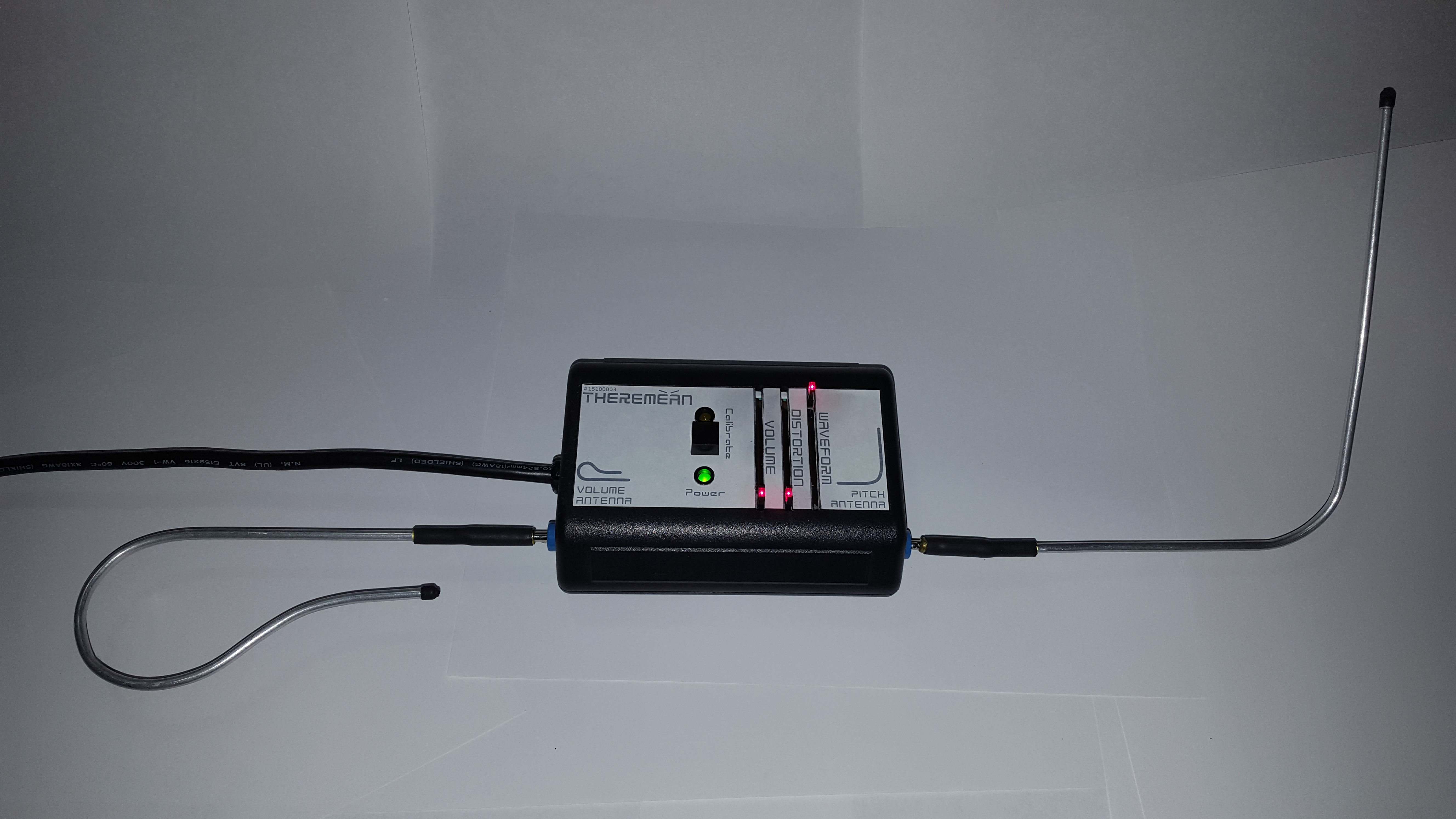
The final product – Behold the Theremean!

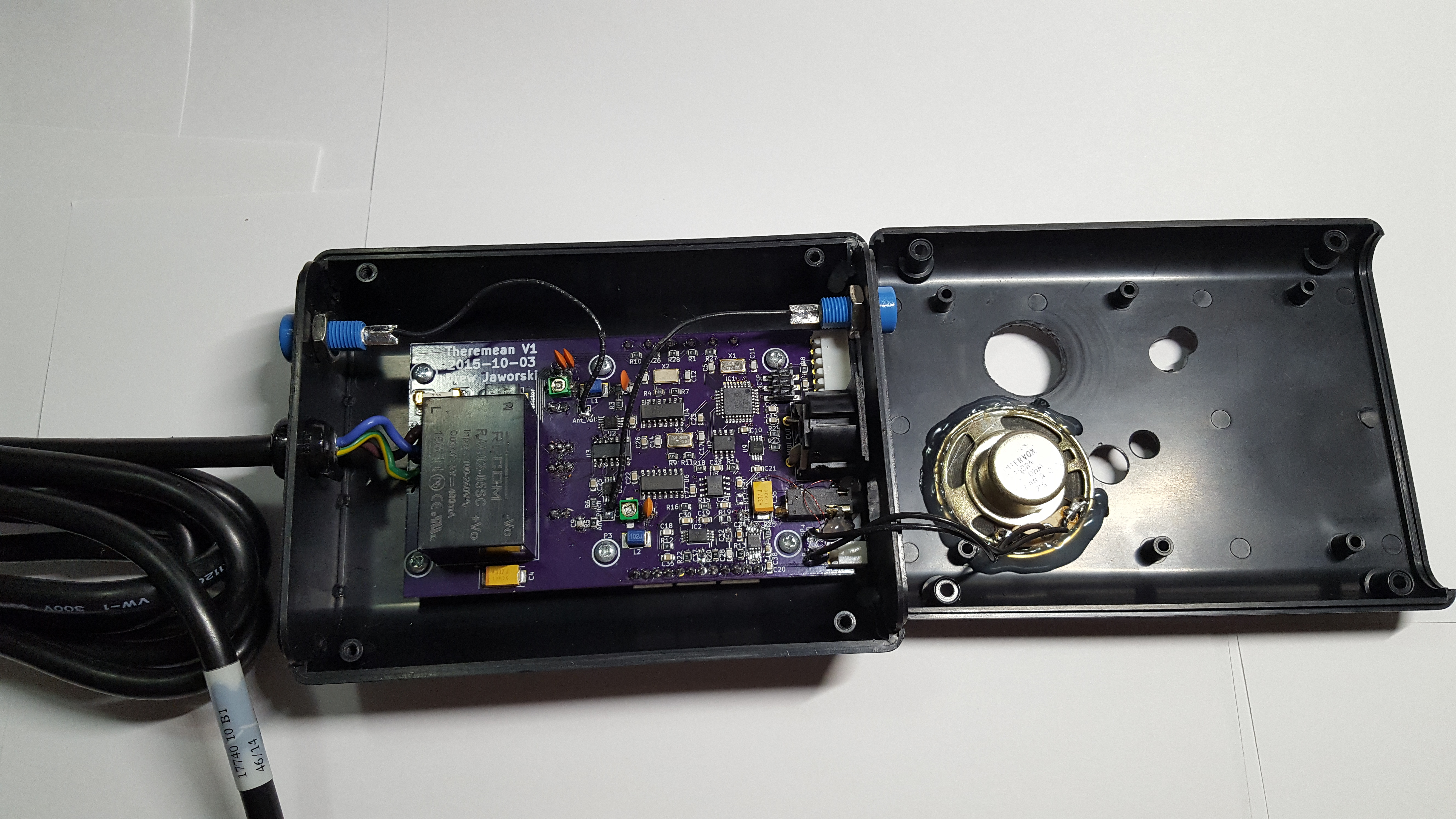
Concept: I wanted a straightforward design with off-the-shelf components and easily-fabricated sub-assemblies, a controlled BOM with a minimum number of vendors and short lead-times. I settled on making a modified version of the Open.Theremin.Uno, in my own plastic case and using a custom PCB with my own design flare. I designed in all the standard/extra features: volume control, waveform selection, a calibrate button, power LED, calibrate LED, CV output, MIDI output, and an internal speaker tied to a switched headphone/line output. I decided to power the unit with a shielded (so it doesn’t interfere with the antennae) line power plug connected to an internal DC power supply module. I used banana plugs to make the antennae easily removable, and, finally, added the unique feature of a built-in distortion output stage (based on the "Mockman 2.0"), which inspired the puntastic name of Theremean!

Picture of the innards

BOM: The Bill of Materials below shows all of the components that went into the final build (but not any tweaks that were made post-production). I broke the cost-per-unit down into 1/10/100 quantities to show how much it might cost if I had chosen to build these in a larger quantity; I ended up building 3 units at a cost of around \(85/ea, knowing that I could build 100 units at a noticeably lower cost of\)58/ea. These numbers are just for reference, though, because it does not account for any capital costs (equipment, solder paste mask), labor (I like to value my time at around $0.00/hr for personal projects; I’m doing this for fun, after all), design time, troubleshooting time, extra parts, electricity, lack of sleep, and anything else I can’t remember (due to lack of sleep?).

(BOM)

Case: The case was a standard plastic case, the JB-35R*0000 from Polycase, which I hand-machined with various holes using step-bits and blades/files. The unit in the pictures here was my first unit, with some extra “oops” holes and access to the programming header. For a larger quantity of builds, I would have paid the ~$100 setup fee to have Polycase machine these for me and add fancy graphic overlays. Instead, I created the design in Inkscape as an overlay of the manufacturer’s dimensioned drawing, and printed it out on large white label stock. After attaching it to the case, I used the black areas as a cutting template.

Front Panel Layout

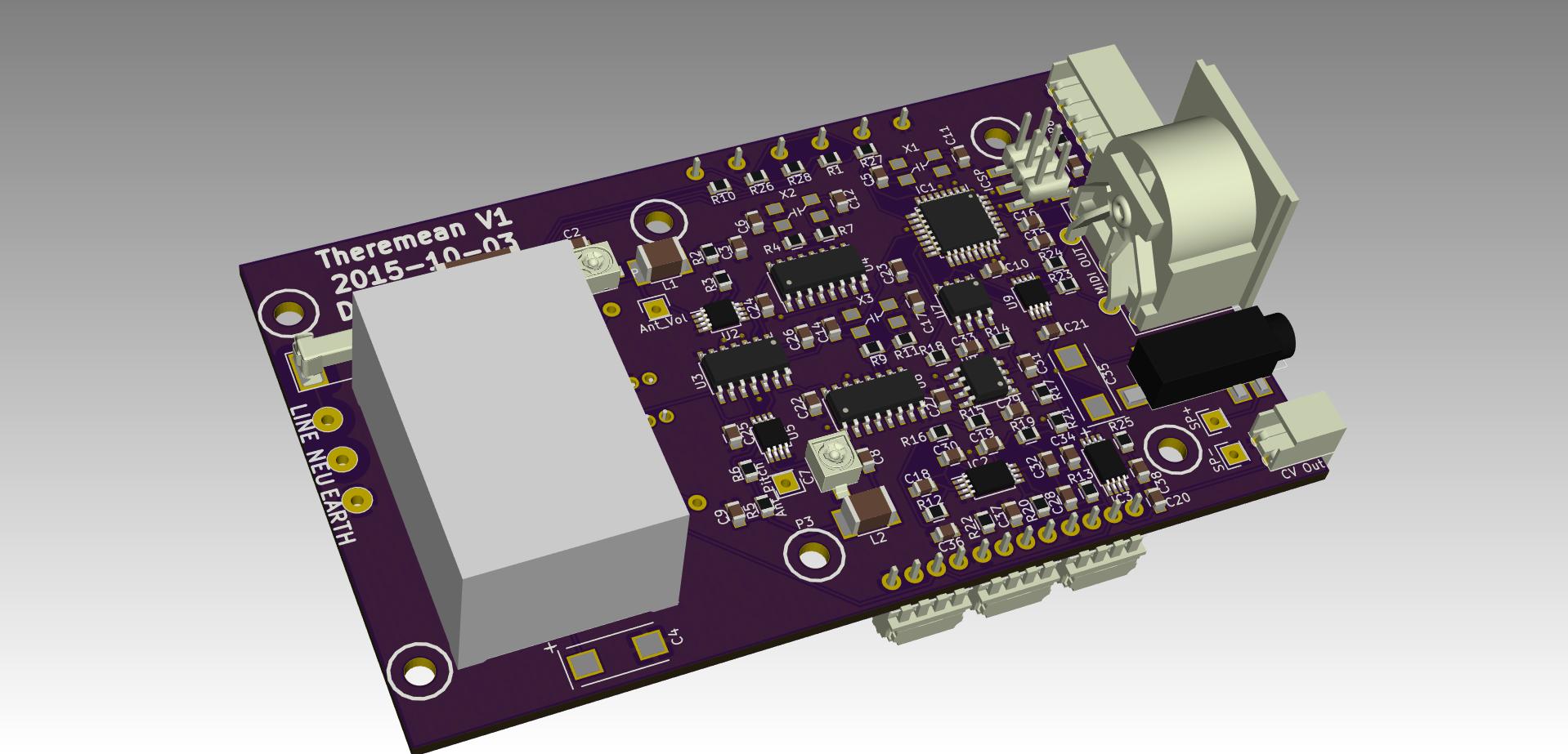
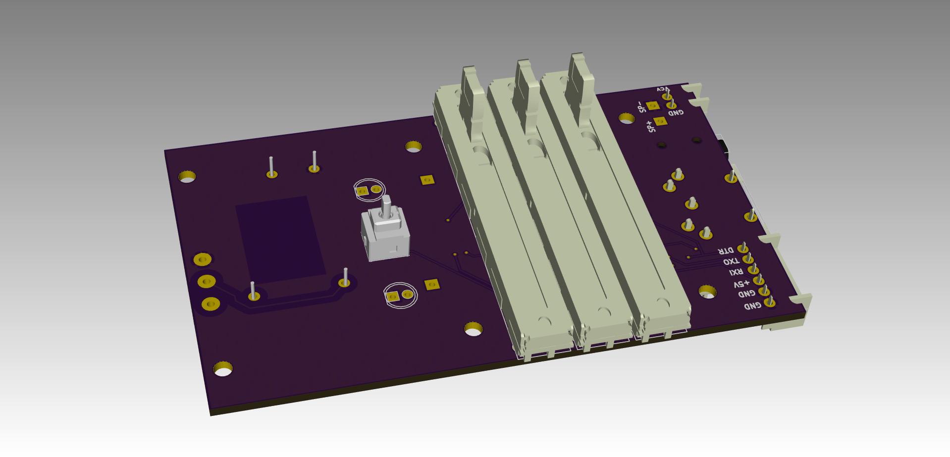
PCB: While I based my KiCAD design on the Open.Theremin.Uno, I made some PCB BOM changes to optimize the components and layout. I also used this as a moment to try my hand at making a board with 0805 passives; while I have experience designing as small as 0402 passives into PCBAs for work, we have those assembled professionally with pick-and-place, and I have never tried something smaller than 1206 for hand-placed SMT work. It turned out fine, and I could have made the layout much tighter if I had wanted to; in fact, in hindsight it looks like I subconsciously left as much spacing as I would have for 1206. I had the PCBs made by the always-awesome OSH Park, and I had a solder paste stencil made by OSH Stencils.

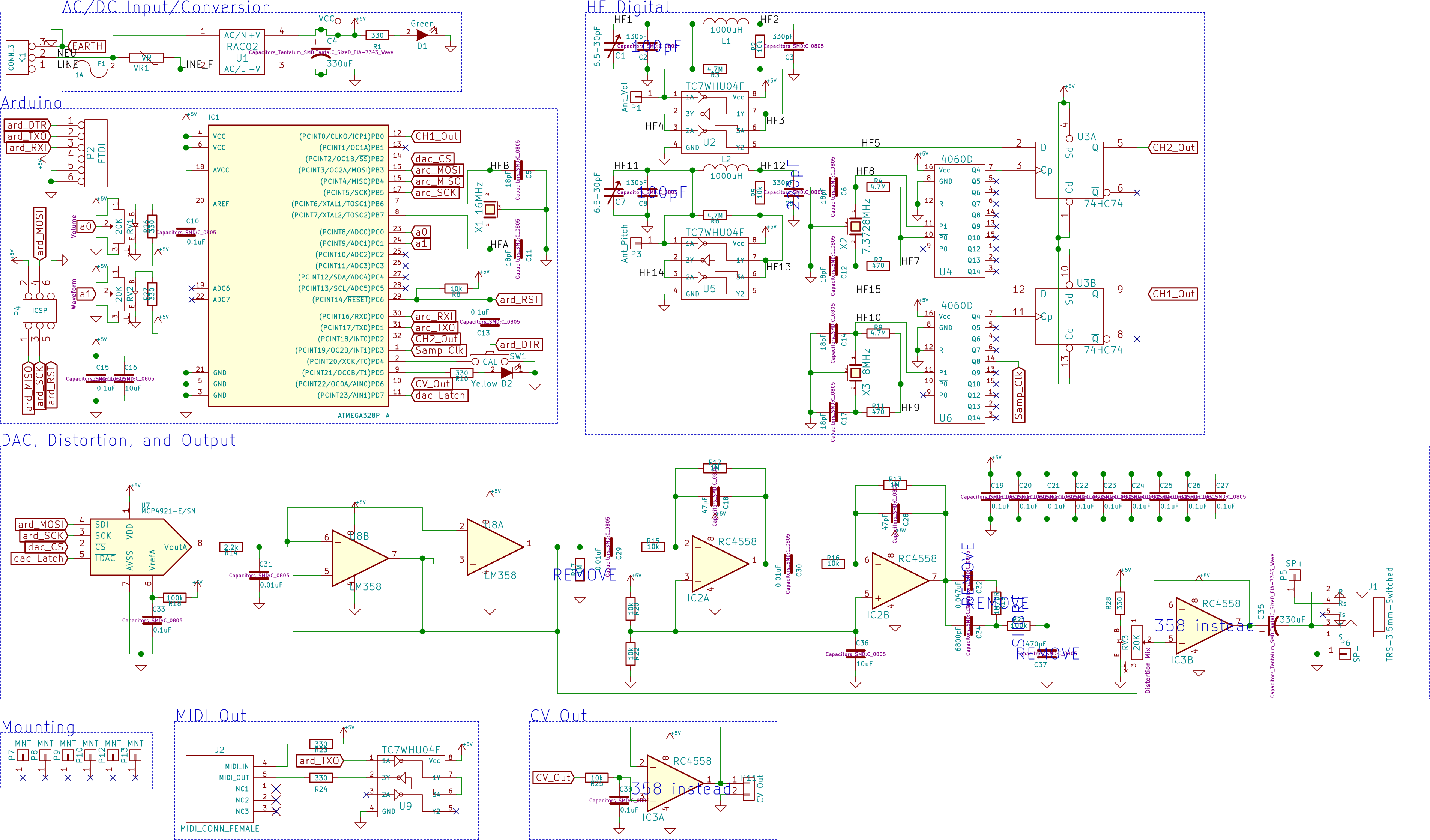
KiCad Schematic
KiCad Rendering – Front
KiCad Rendering – Back

Other Notes: The antennae were made from 5/32″ OD (0.128″ ID) aluminum tubes, hand-shaped and soldered to banana plugs, with some adhesive heatshrink for protection and looks. The mating blue banana jacks were used because I had them on hand already, and I used slider potentiometers with LEDs just to give it some color. I used the original Open.Theremin.Uno Arduino code without any memorable issues; I may have added a few tweaks, I can’t remember.

The distortion effect gave me some trouble; I based it on some guitar effects designs I found online, but after the build I discovered some items that needed to be changed, which are noted on the schematic.

I had some trouble with the original tank capacitor values (probably since they were selected for a different PCB design with its own internal capacitances), so I had to solder in some other values in parallel to give me the capacitance I needed to calibrate the unit correctly. An improvement in the future would be to add a digital capacitor IC (a switched capacitor bank, essentially) to allow the calibration to be automatic, because it was rather finicky.

I am happy with the final product. I kept the first one, gave one to my Mom, and gave one to my friend Sean.

UPDATE: Since the completion of this project, an Open.Theremin.V3 has been released with some newer features; most importantly, the automatic calibration that I wanted to include. But they did it with a tuned diode, instead of a switched capacitor bank (digital capacitor) like I proposed.

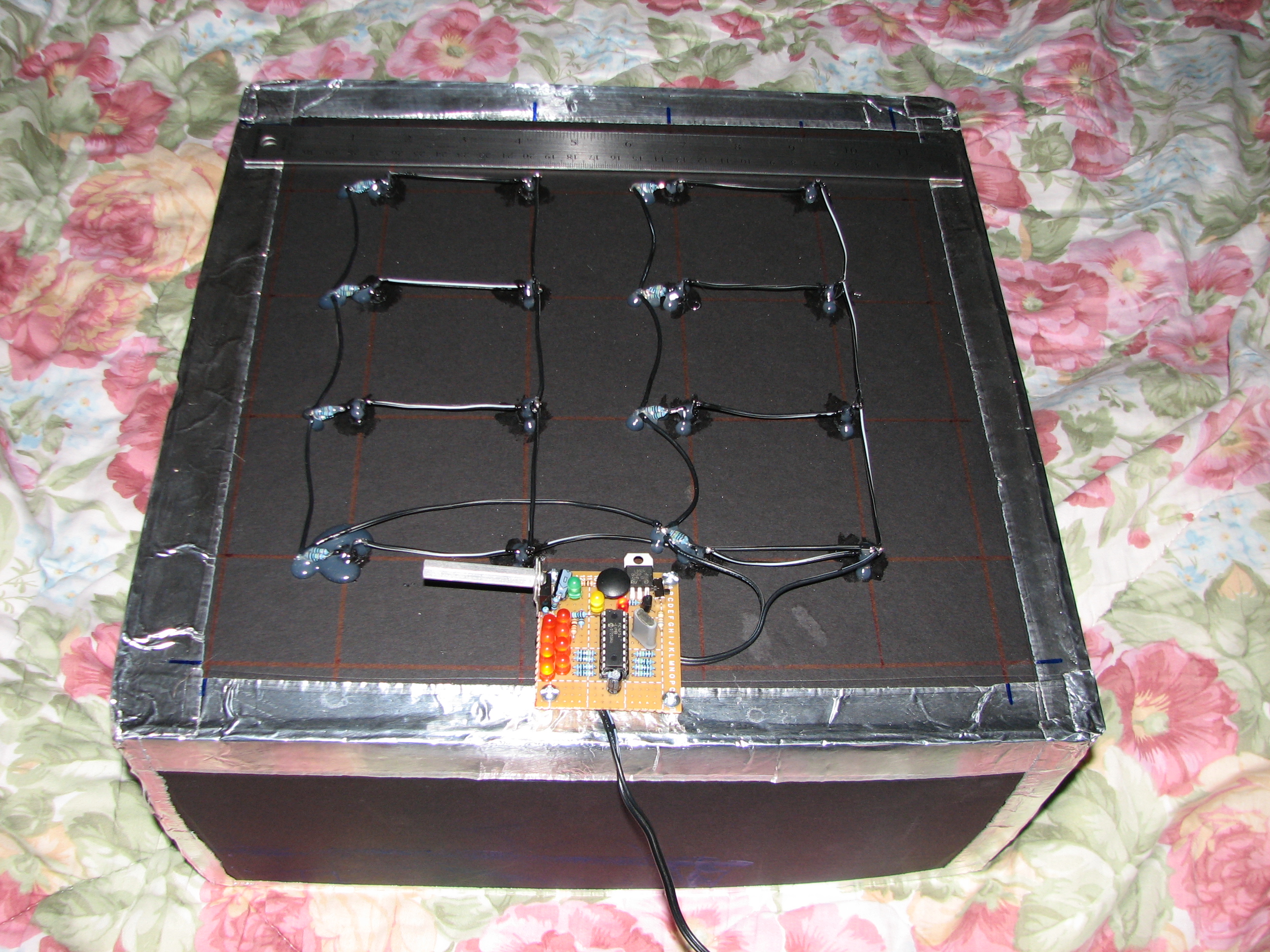
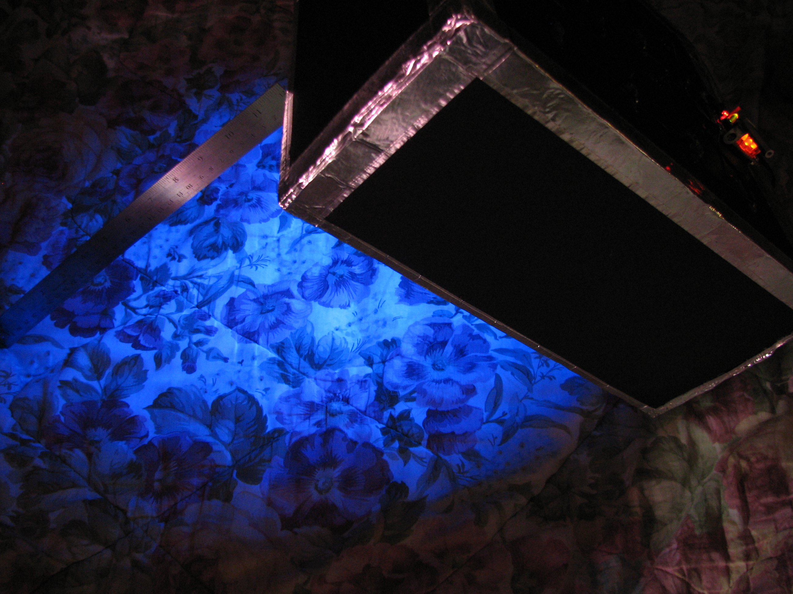
Top of the box with a ruler for scale.

I just finished designing and building a (12.5″)x(12.5″)x(6″) ultraviolet light box with a pic16f54 microcontroller programmed as a timer for the exposure. It was made mostly to be a UV light source for exposing photosensitive film used as an etch-resist in the process of making printed circuit boards. It can also be used as a weapon against vampires.

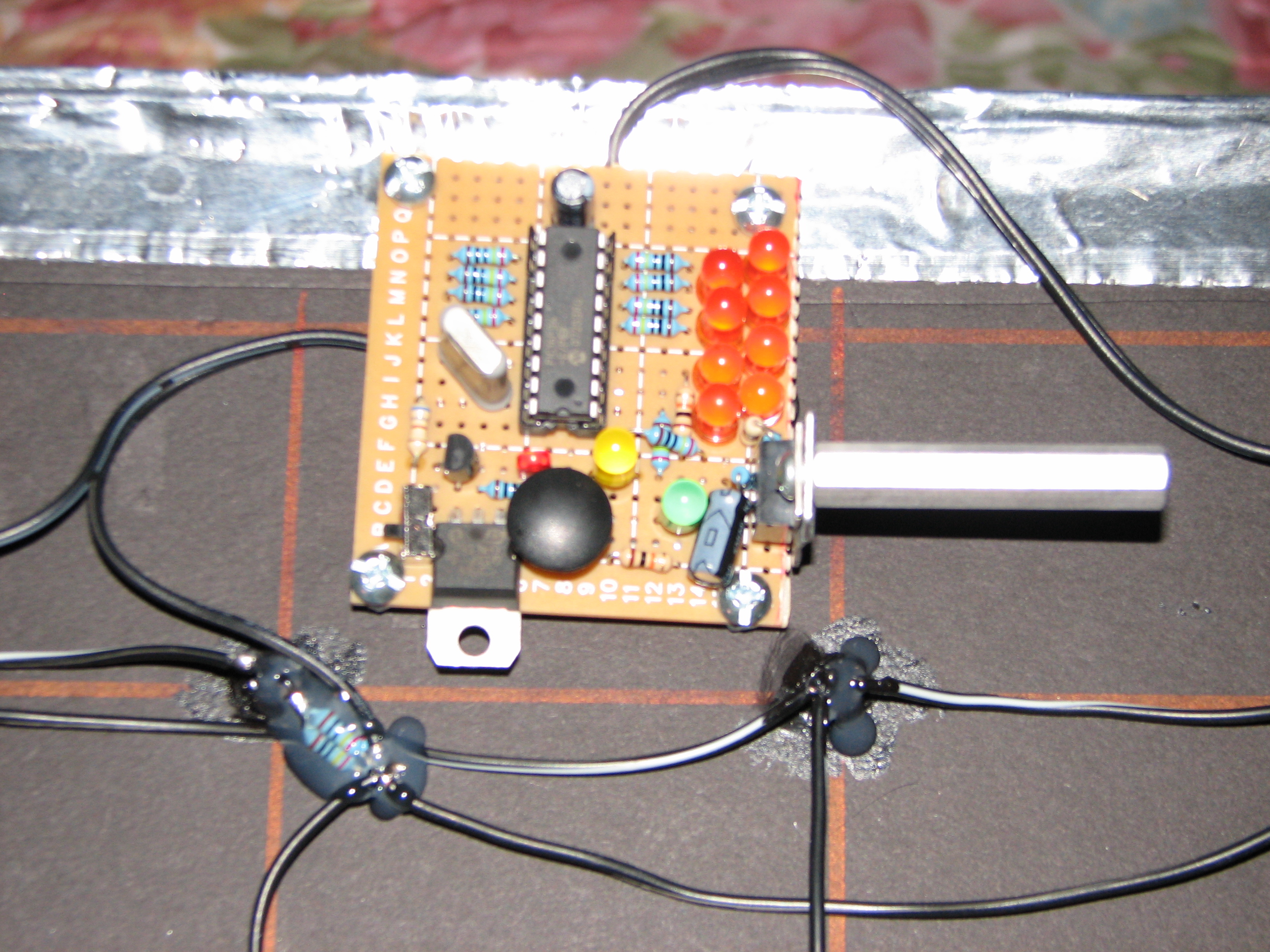
Close-up of the controller board (upside down!)

The red LED indicates power is connected to the microcontroller (controlled by the small switch in the corner or just by unplugging the wall-wart). Pressing the round black button adds 30 seconds two minutes to the timer, which is indicated in binary on with the 8 orange LEDs; it is limited to 255 seconds (4 minutes, 15 seconds) and suffers overrun if you press the button enough times 16 minutes and doesn’t loop back to zero. Power is applied to the ultraviolet LEDS whenever the timer is greater than zero, which can be indicated by (a) the yellow LED indicating the UV lights are on, (b) the green led blinking once per second as the timer counts down, or (c) the bottom of the box emitting a faint blue glow. The assembly code I spent an afternoon writing can be found at the bottom of this post, if you are curious (My first real ASM program! It was actually kinda fun!).

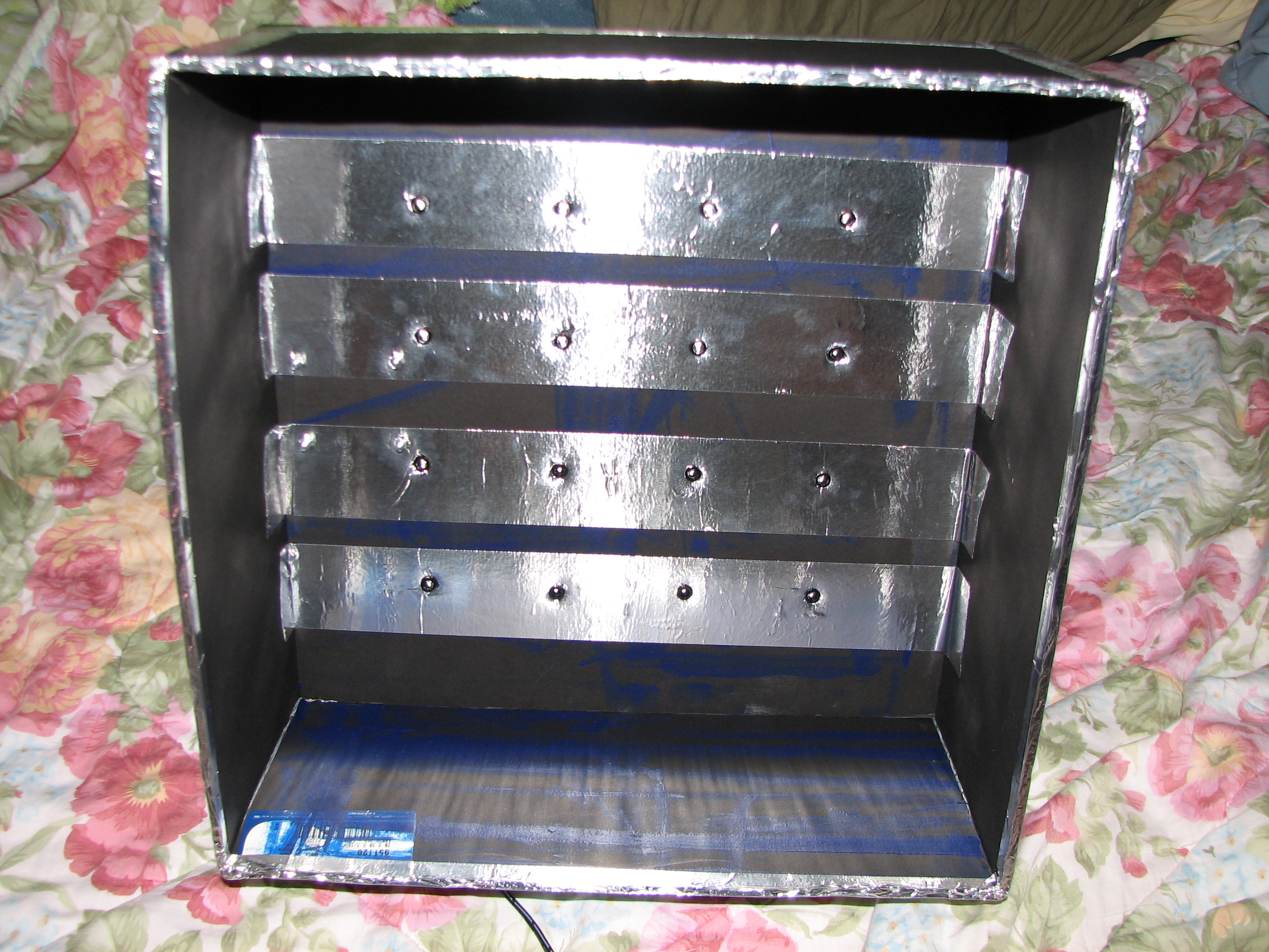
Inside of the light box; still not sure what the cat likes about this place, but he sure likes trying to get in there.

Measurements indicated that the ultraviolet LEDs are using 29.1[mA] each, so the box should be outputting a total luminous intensity of \([16 * (1.375 * 80[mcd])]= 1.76[cd]\) at wavelengths between 350[nm]-420[nm] (peak @~380[nm]). The photoresist film that I use has an exposure sensitivity between 315[nm]-400[nm], with a peak response at 355[nm]-380[nm], which fits nicely with the LED selection.

The UV LED array has a square spacing of 2.5″, meaning the center of four adjacent LEDs is \({2.5[in] * sqrt{2} over 2} = 1.7677[in]\) away from any given led. Using the Radiation Diagram from the datasheet, the minimum surface distance from the tip of the LEDs at which the light cone would be at 25% intensity at these centers is then \({{tan (20,^{circ})} over 1.7677[in]} = 4.8569[in]\). I interpret this as the minimum distance an object needs to be from the UV LEDs in order for the light to be relatively uniform across the whole surface. Beyond this distance, it should become even more uniform; fortunately, my two glass plates, a standard 1/16″ copper clad board, photoresist film, and artwork transparencies add up just under 3/8″, so all is well for my application. The largest copper clad board I ever plan to use is 8″x10″, so my 2.5″ spacing works to keep the UV light at a decent intensity on the edges. UPDATE: Unfortunately, this is not the case, as tests have shown that the board needs to be at least another 1/2 inch from the LEDs. This may have something to do with where you measure from, exactly, but there are visibly contrasting regions visible on a white sheet of paper. The solution I have in mind will be to simply extend the bottom of the box.

Just showing off the light emission.
  1. ; Timer for UV Light Box Control
  2. ; Initially off. Waits for input to set length of ON time, waits for lack of input, then starts. PORTB acts as indicator of number of 2xminutes to set timer.
  3. ; PIC16F54 @ 3.579545 MHz
  4. ; Drew Jaworski 2012
  5. include

  6. __CONFIG _HS_OSC & _WDT_OFF & _CP_OFF
  7. UDATA
  8. ; delay counter vars
  9. dc1 res 1
  10. dc2 res 1
  11. dc3 res 1
  12. ptm res 1 ; 120 second run timer
  13. PROG CODE
  14. init
  15. movlw b'11110010' ;RA0 is UV control output, RA1 is timer increment button input (active low), RA2 is clock indicator LED output, RA3 is UV on indicator
  16. tris PORTA
  17. movlw 0x00 ;RB7-RB0 are time display outputs
  18. tris PORTB
  19. start
  20. movlw 0x00 ;set all outputs OFF initially
  21. movwf PORTA
  22. movlw 0x00 ;initial time to display
  23. movwf PORTB
  24. movlw 0x78 ; initial 2xminute run timer setting (120)
  25. movwf ptm
  26. wait_start
  27. btfsc PORTA,b'001' ;check button status
  28. goto wait_start ;skip back if button was not pressed
  29. wait_input
  30. ;delay 0.25 seconds
  31. movlw 0xC7
  32. movwf dc1
  33. movlw 0xAF
  34. movwf dc2
  35. Delay_2
  36. decfsz dc1, f
  37. goto $+2
  38. decfsz dc2, f
  39. goto Delay_2
  40. ;end delay
  41. btfsc PORTA,b'001' ;check button status
  42. goto begin_run_timer;start if button was not pressed
  43. btfsc PORTB,b'000'
  44. goto $+3
  45. bsf PORTB,b'000'
  46. goto wait_input
  47. btfsc PORTB,b'001'
  48. goto $+3
  49. bsf PORTB,b'001'
  50. goto wait_input
  51. btfsc PORTB,b'010'
  52. goto $+3
  53. bsf PORTB,b'010'
  54. goto wait_input
  55. btfsc PORTB,b'011'
  56. goto $+3
  57. bsf PORTB,b'011'
  58. goto wait_input
  59. btfsc PORTB,b'100'
  60. goto $+3
  61. bsf PORTB,b'100'
  62. goto wait_input
  63. btfsc PORTB,b'101'
  64. goto $+3
  65. bsf PORTB,b'101'
  66. goto wait_input
  67. btfsc PORTB,b'110'
  68. goto $+3
  69. bsf PORTB,b'110'
  70. goto wait_input
  71. btfsc PORTB,b'111'
  72. goto wait_input
  73. bsf PORTB,b'111'
  74. goto wait_input
  75. begin_run_timer
  76. bsf PORTA,b'000'
  77. bsf PORTA,b'011'
  78. run_timer
  79. ;delay 0.5 seconds
  80. movlw 0xAF
  81. movwf dc1
  82. movlw 0xFA
  83. movwf dc2
  84. movlw 0x01
  85. movwf dc3
  86. Delay_0
  87. decfsz dc1, f
  88. goto $+2
  89. decfsz dc2, f
  90. goto $+2
  91. decfsz dc3, f
  92. goto Delay_0
  93. goto $+1
  94. goto $+1
  95. nop
  96. ;end delay
  97. bsf PORTA,b'010' ;set led
  98. ;delay 0.5 seconds
  99. movlw 0xAF
  100. movwf dc1
  101. movlw 0xFA
  102. movwf dc2
  103. movlw 0x01
  104. movwf dc3
  105. Delay_1
  106. decfsz dc1, f
  107. goto $+2
  108. decfsz dc2, f
  109. goto $+2
  110. decfsz dc3, f
  111. goto Delay_1
  112. goto $+1
  113. goto $+1
  114. nop
  115. ;end delay
  116. bcf PORTA,b'010' ;clear led
  117. decfsz ptm,f ; decrement run_timer
  118. goto run_timer ;continue next cycle if iwt decrement result was not zero
  119. movlw 0x78
  120. movwf ptm ;reset run timer if it hit zero
  121. ;also remove a minute from timer
  122. btfss PORTB,b'111'
  123. goto $+3
  124. bcf PORTB,b'111'
  125. goto run_timer
  126. btfss PORTB,b'110'
  127. goto $+3
  128. bcf PORTB,b'110'
  129. goto run_timer
  130. btfss PORTB,b'101'
  131. goto $+3
  132. bcf PORTB,b'101'
  133. goto run_timer
  134. btfss PORTB,b'100'
  135. goto $+3
  136. bcf PORTB,b'100'
  137. goto run_timer
  138. btfss PORTB,b'011'
  139. goto $+3
  140. bcf PORTB,b'011'
  141. goto run_timer
  142. btfss PORTB,b'010'
  143. goto $+3
  144. bcf PORTB,b'010'
  145. goto run_timer
  146. btfss PORTB,b'001'
  147. goto $+3
  148. bcf PORTB,b'001'
  149. goto run_timer
  150. btfss PORTB,b'000'
  151. goto run_timer
  152. bcf PORTB,b'000'
  153. goto start ;reset everything if time has run out
  154. END

As part of my Senior Design II class, I gave an oral presentation (as opposed to my option of compiling and presenting a poster) at the 14th Annual Research Symposium at my University, and won 1st place out of 8 presentations! In lieu of the actual presentation from that day, here is a link to the Final Presentation I gave for my Senior Design Project in May 2012, including the text notes I prepared to remind myself what I intended to say on each slide (despite the fact that I did not get to use them in any way during the actual presentation). I have also embedded it below:

PDF-Js: Could not resolve file name '2012-05-04-FINALPRESENTATIONJAWORSKI.pdf'.

Finally got my website back up this weekend! I am now using a very minimal (non-database) CMS called Grav. It is not user-friendly at first, but once you read the documentation, it is easy to understand. I don't like it, honestly, because despite its simplicity, it is both very easy to mess up things and very difficult to do specific things at the same time. Almost to the point where I want something so minimal, I might as well be handcoding the HTML/CSS (or, at least, just simply "compiling" the output, stripping out what I don't want, and just serving the static files. In the end, this gives me a nice interface for entering posts, at least.

I have been using RamNode for a very minimal VPS for a few years now; they seem to be a reliable service provider (read: they regularly pay their Data Center subleases). I'm paying US$15.00/year for their "128MB SVZ" plan (OpenVZ SSD VPS), which is signifcantly less than I'd be paying for actual internet and electricity/cooling for a home server (I am not even going to bother to back that up with numbers here).:

  • 128MB RAM
  • 1 CPU Core Access
  • 12GB SSD Space
  • 1Gbps Port, 500GB Bandwidth
  • 1 IPv4 Address, /64 IPv6, TUN/TAP

HOWEVER, I wasted several days of trial and error trying to get a normal SQL/etc-database-based CMS to work, and I could just never get the database aspect to work properly in Ubuntu OR Debian. I went through that cycle three times in the past year and still never got it working, so now I am here with Grav. :)