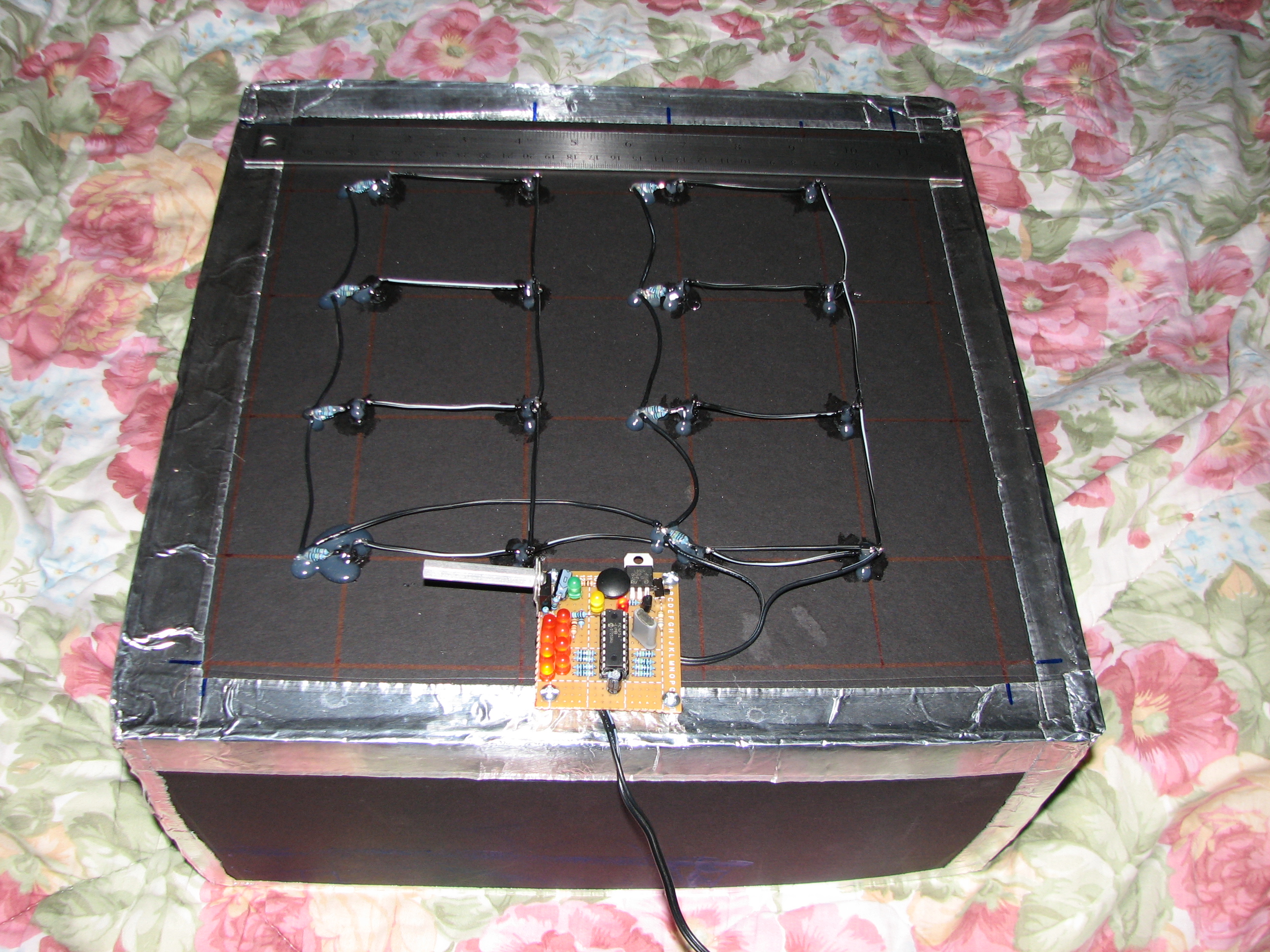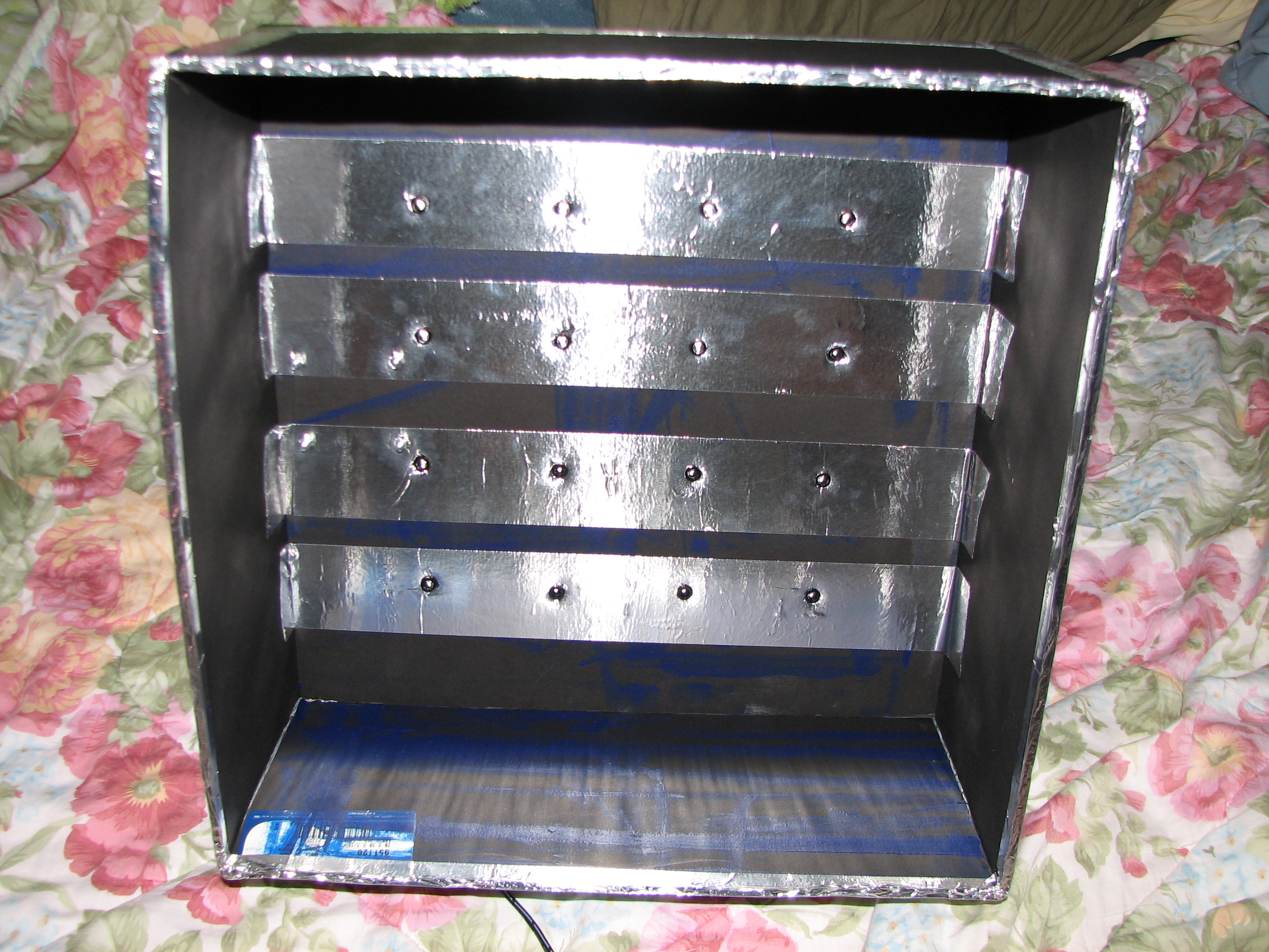
I just finished designing and building a (12.5″)x(12.5″)x(6″) ultraviolet light box with a pic16f54 microcontroller programmed as a timer for the exposure. It was made mostly to be a UV light source for exposing photosensitive film used as an etch-resist in the process of making printed circuit boards. It can also be used as a weapon against vampires.

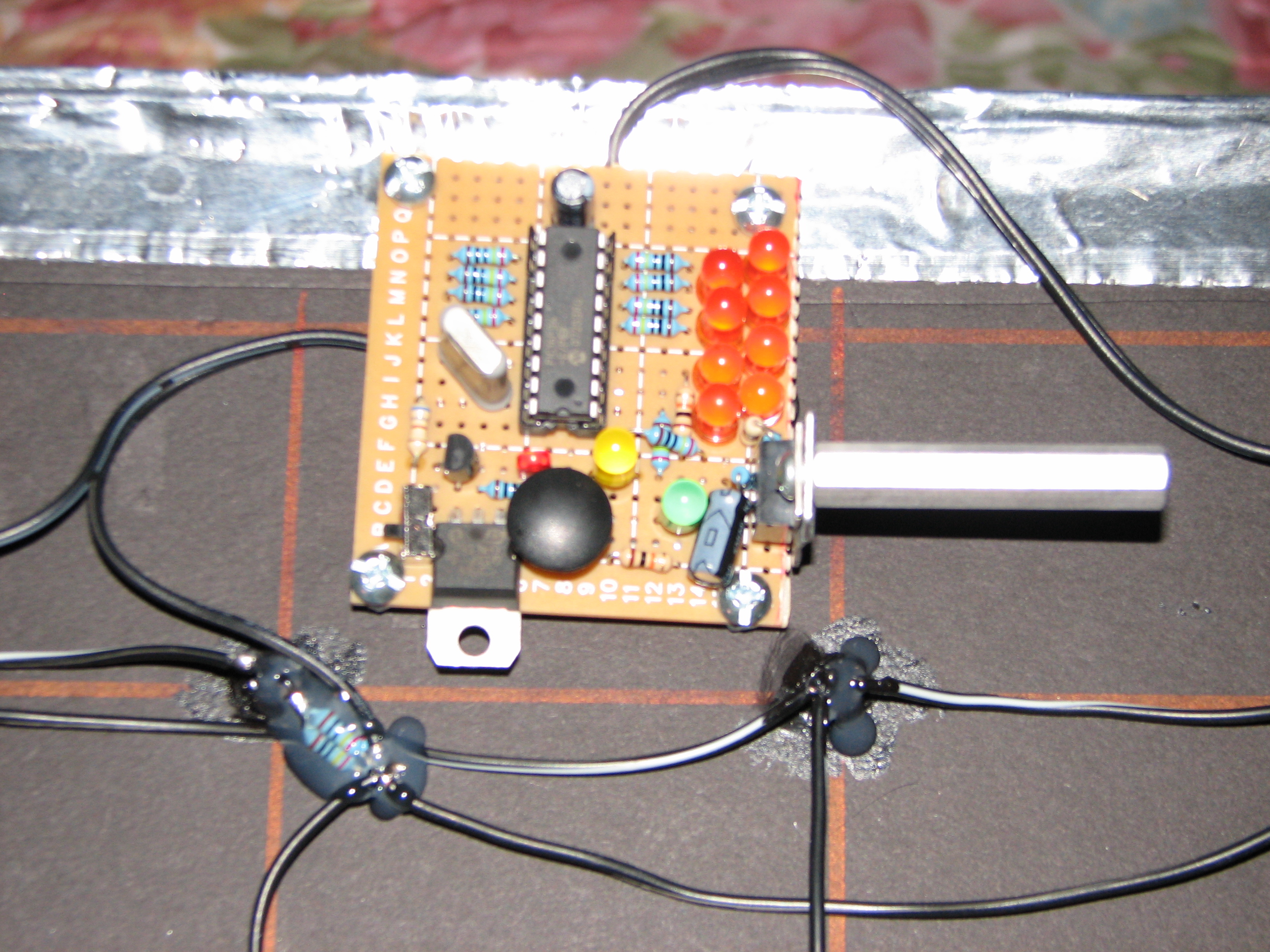
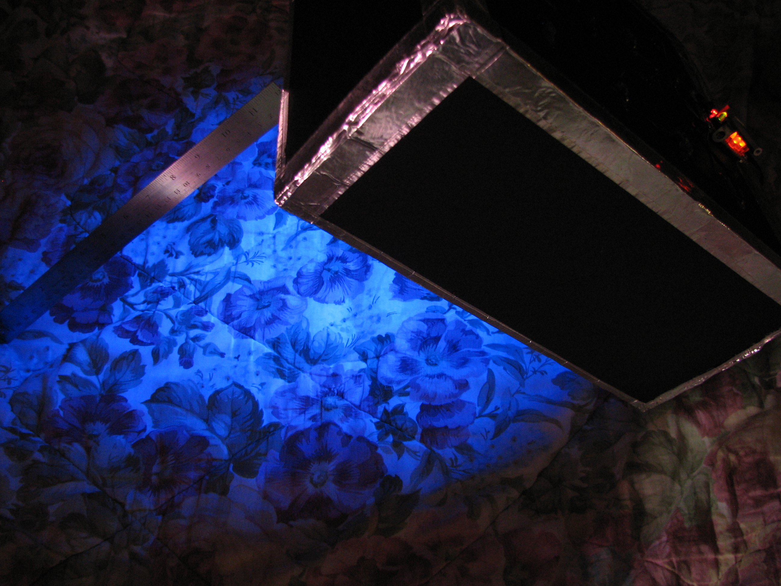
The red LED indicates power is connected to the microcontroller (controlled by the small switch in the corner or just by unplugging the wall-wart). Pressing the round black button adds 30 seconds two minutes to the timer, which is indicated in binary on with the 8 orange LEDs; it is limited to 255 seconds (4 minutes, 15 seconds) and suffers overrun if you press the button enough times 16 minutes and doesn’t loop back to zero. Power is applied to the ultraviolet LEDS whenever the timer is greater than zero, which can be indicated by (a) the yellow LED indicating the UV lights are on, (b) the green led blinking once per second as the timer counts down, or (c) the bottom of the box emitting a faint blue glow. The assembly code I spent an afternoon writing can be found at the bottom of this post, if you are curious (My first real ASM program! It was actually kinda fun!).

Measurements indicated that the ultraviolet LEDs are using 29.1[mA] each, so the box should be outputting a total luminous intensity of \([16 * (1.375 * 80[mcd])]= 1.76[cd]\) at wavelengths between 350[nm]-420[nm] (peak @~380[nm]). The photoresist film that I use has an exposure sensitivity between 315[nm]-400[nm], with a peak response at 355[nm]-380[nm], which fits nicely with the LED selection.
The UV LED array has a square spacing of 2.5″, meaning the center of four adjacent LEDs is \({2.5[in] * sqrt{2} over 2} = 1.7677[in]\) away from any given led. Using the Radiation Diagram from the datasheet, the minimum surface distance from the tip of the LEDs at which the light cone would be at 25% intensity at these centers is then \({{tan (20,^{circ})} over 1.7677[in]} = 4.8569[in]\). I interpret this as the minimum distance an object needs to be from the UV LEDs in order for the light to be relatively uniform across the whole surface. Beyond this distance, it should become even more uniform; fortunately, my two glass plates, a standard 1/16″ copper clad board, photoresist film, and artwork transparencies add up just under 3/8″, so all is well for my application. The largest copper clad board I ever plan to use is 8″x10″, so my 2.5″ spacing works to keep the UV light at a decent intensity on the edges. UPDATE: Unfortunately, this is not the case, as tests have shown that the board needs to be at least another 1/2 inch from the LEDs. This may have something to do with where you measure from, exactly, but there are visibly contrasting regions visible on a white sheet of paper. The solution I have in mind will be to simply extend the bottom of the box.

- ; Timer for UV Light Box Control
- ; Initially off. Waits for input to set length of ON time, waits for lack of input, then starts. PORTB acts as indicator of number of 2xminutes to set timer.
- ; PIC16F54 @ 3.579545 MHz
- ; Drew Jaworski 2012
include
- __CONFIG _HS_OSC & _WDT_OFF & _CP_OFF
- UDATA
- ; delay counter vars
- dc1 res 1
- dc2 res 1
- dc3 res 1
- ptm res 1 ; 120 second run timer
- PROG CODE
- init
- movlw b'11110010' ;RA0 is UV control output, RA1 is timer increment button input (active low), RA2 is clock indicator LED output, RA3 is UV on indicator
- tris PORTA
- movlw 0x00 ;RB7-RB0 are time display outputs
- tris PORTB
- start
- movlw 0x00 ;set all outputs OFF initially
- movwf PORTA
- movlw 0x00 ;initial time to display
- movwf PORTB
- movlw 0x78 ; initial 2xminute run timer setting (120)
- movwf ptm
- wait_start
- btfsc PORTA,b'001' ;check button status
- goto wait_start ;skip back if button was not pressed
- wait_input
- ;delay 0.25 seconds
- movlw 0xC7
- movwf dc1
- movlw 0xAF
- movwf dc2
- Delay_2
- decfsz dc1, f
- goto $+2
- decfsz dc2, f
- goto Delay_2
- ;end delay
- btfsc PORTA,b'001' ;check button status
- goto begin_run_timer;start if button was not pressed
- btfsc PORTB,b'000'
- goto $+3
- bsf PORTB,b'000'
- goto wait_input
- btfsc PORTB,b'001'
- goto $+3
- bsf PORTB,b'001'
- goto wait_input
- btfsc PORTB,b'010'
- goto $+3
- bsf PORTB,b'010'
- goto wait_input
- btfsc PORTB,b'011'
- goto $+3
- bsf PORTB,b'011'
- goto wait_input
- btfsc PORTB,b'100'
- goto $+3
- bsf PORTB,b'100'
- goto wait_input
- btfsc PORTB,b'101'
- goto $+3
- bsf PORTB,b'101'
- goto wait_input
- btfsc PORTB,b'110'
- goto $+3
- bsf PORTB,b'110'
- goto wait_input
- btfsc PORTB,b'111'
- goto wait_input
- bsf PORTB,b'111'
- goto wait_input
- begin_run_timer
- bsf PORTA,b'000'
- bsf PORTA,b'011'
- run_timer
- ;delay 0.5 seconds
- movlw 0xAF
- movwf dc1
- movlw 0xFA
- movwf dc2
- movlw 0x01
- movwf dc3
- Delay_0
- decfsz dc1, f
- goto $+2
- decfsz dc2, f
- goto $+2
- decfsz dc3, f
- goto Delay_0
- goto $+1
- goto $+1
- nop
- ;end delay
- bsf PORTA,b'010' ;set led
- ;delay 0.5 seconds
- movlw 0xAF
- movwf dc1
- movlw 0xFA
- movwf dc2
- movlw 0x01
- movwf dc3
- Delay_1
- decfsz dc1, f
- goto $+2
- decfsz dc2, f
- goto $+2
- decfsz dc3, f
- goto Delay_1
- goto $+1
- goto $+1
- nop
- ;end delay
- bcf PORTA,b'010' ;clear led
- decfsz ptm,f ; decrement run_timer
- goto run_timer ;continue next cycle if iwt decrement result was not zero
- movlw 0x78
- movwf ptm ;reset run timer if it hit zero
- ;also remove a minute from timer
- btfss PORTB,b'111'
- goto $+3
- bcf PORTB,b'111'
- goto run_timer
- btfss PORTB,b'110'
- goto $+3
- bcf PORTB,b'110'
- goto run_timer
- btfss PORTB,b'101'
- goto $+3
- bcf PORTB,b'101'
- goto run_timer
- btfss PORTB,b'100'
- goto $+3
- bcf PORTB,b'100'
- goto run_timer
- btfss PORTB,b'011'
- goto $+3
- bcf PORTB,b'011'
- goto run_timer
- btfss PORTB,b'010'
- goto $+3
- bcf PORTB,b'010'
- goto run_timer
- btfss PORTB,b'001'
- goto $+3
- bcf PORTB,b'001'
- goto run_timer
- btfss PORTB,b'000'
- goto run_timer
- bcf PORTB,b'000'
- goto start ;reset everything if time has run out
- END