I began this project with the intention of creating a Theremin for my Mom, who has also been fascinated by the instrument but never had one. I have seen a lot of designs ranging from very simple to very complex, but I wanted to make something something… different. I intended to approach this project with a structured mindset in order to test my engineering abilities to follow through on a design from inception to completion.
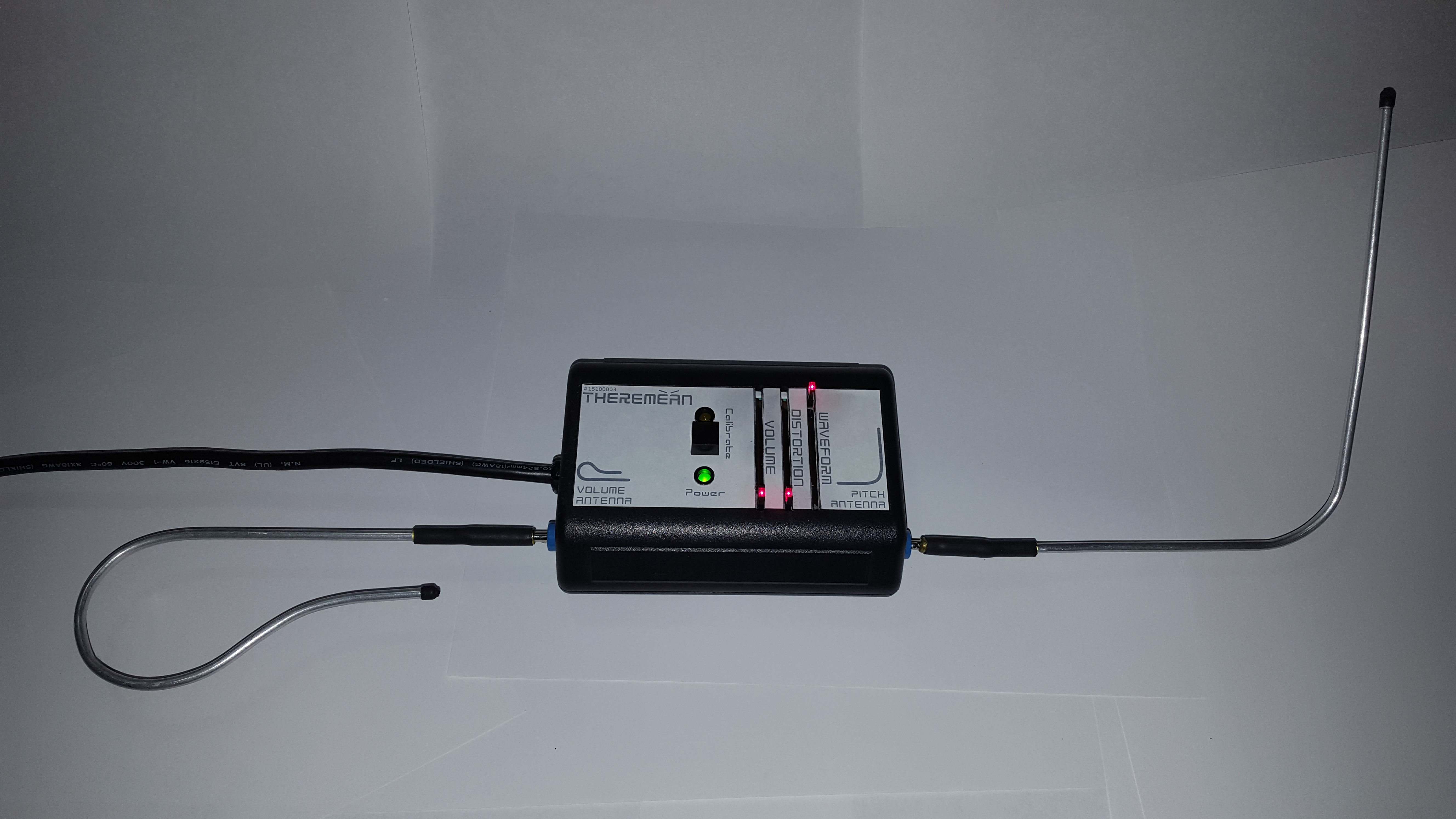
Concept: I wanted a straightforward design with off-the-shelf components and easily-fabricated sub-assemblies, a controlled BOM with a minimum number of vendors and short lead-times. I settled on making a modified version of the Open.Theremin.Uno, in my own plastic case and using a custom PCB with my own design flare. I designed in all the standard/extra features: volume control, waveform selection, a calibrate button, power LED, calibrate LED, CV output, MIDI output, and an internal speaker tied to a switched headphone/line output. I decided to power the unit with a shielded (so it doesn’t interfere with the antennae) line power plug connected to an internal DC power supply module. I used banana plugs to make the antennae easily removable, and, finally, added the unique feature of a built-in distortion output stage (based on the "Mockman 2.0"), which inspired the puntastic name of Theremean!
BOM: The Bill of Materials below shows all of the components that went into the final build (but not any tweaks that were made post-production). I broke the cost-per-unit down into 1/10/100 quantities to show how much it might cost if I had chosen to build these in a larger quantity; I ended up building 3 units at a cost of around \(85/ea, knowing that I could build 100 units at a noticeably lower cost of\)58/ea. These numbers are just for reference, though, because it does not account for any capital costs (equipment, solder paste mask), labor (I like to value my time at around $0.00/hr for personal projects; I’m doing this for fun, after all), design time, troubleshooting time, extra parts, electricity, lack of sleep, and anything else I can’t remember (due to lack of sleep?).
(BOM)
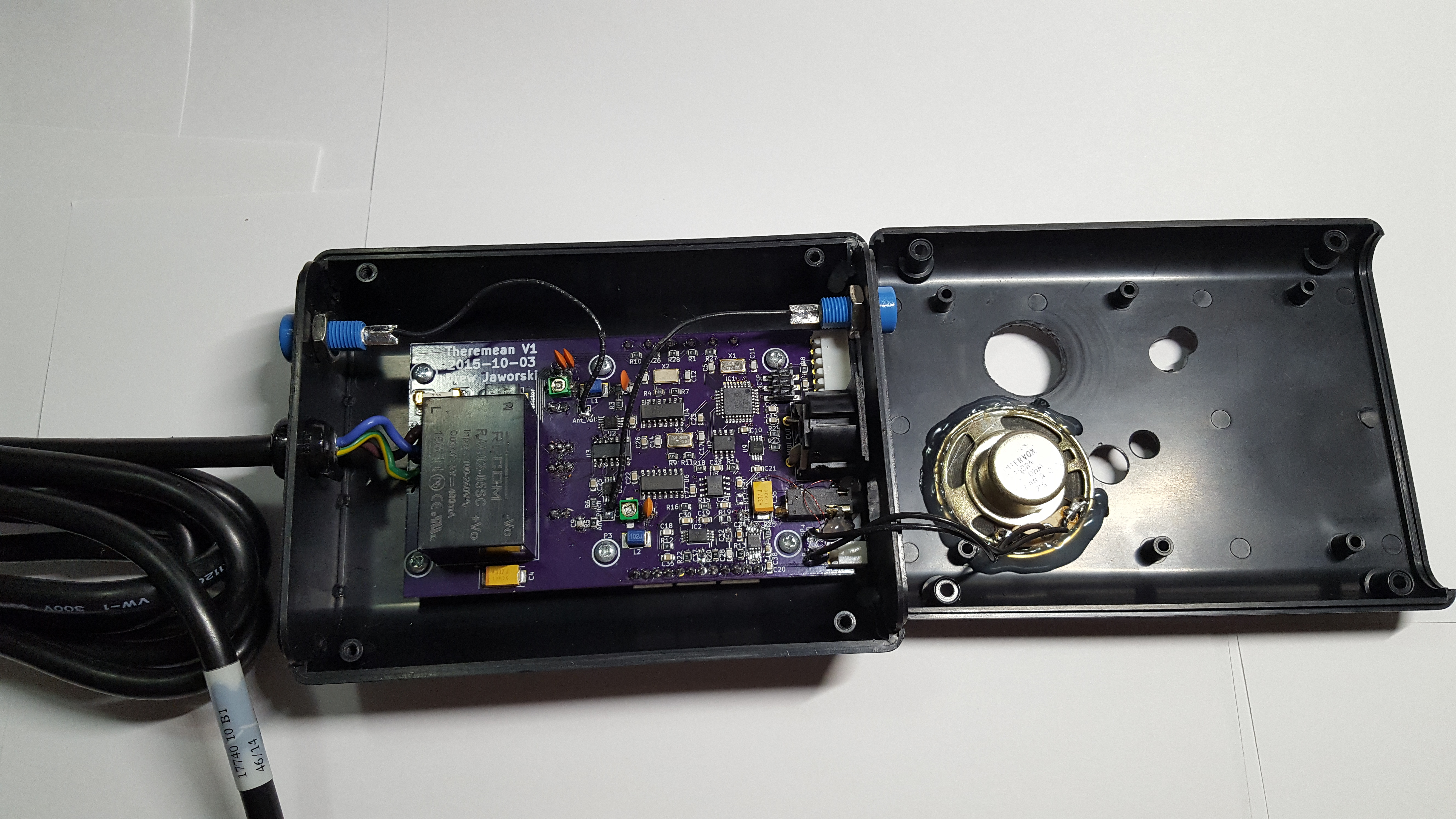
Case: The case was a standard plastic case, the JB-35R*0000 from Polycase, which I hand-machined with various holes using step-bits and blades/files. The unit in the pictures here was my first unit, with some extra “oops” holes and access to the programming header. For a larger quantity of builds, I would have paid the ~$100 setup fee to have Polycase machine these for me and add fancy graphic overlays. Instead, I created the design in Inkscape as an overlay of the manufacturer’s dimensioned drawing, and printed it out on large white label stock. After attaching it to the case, I used the black areas as a cutting template.

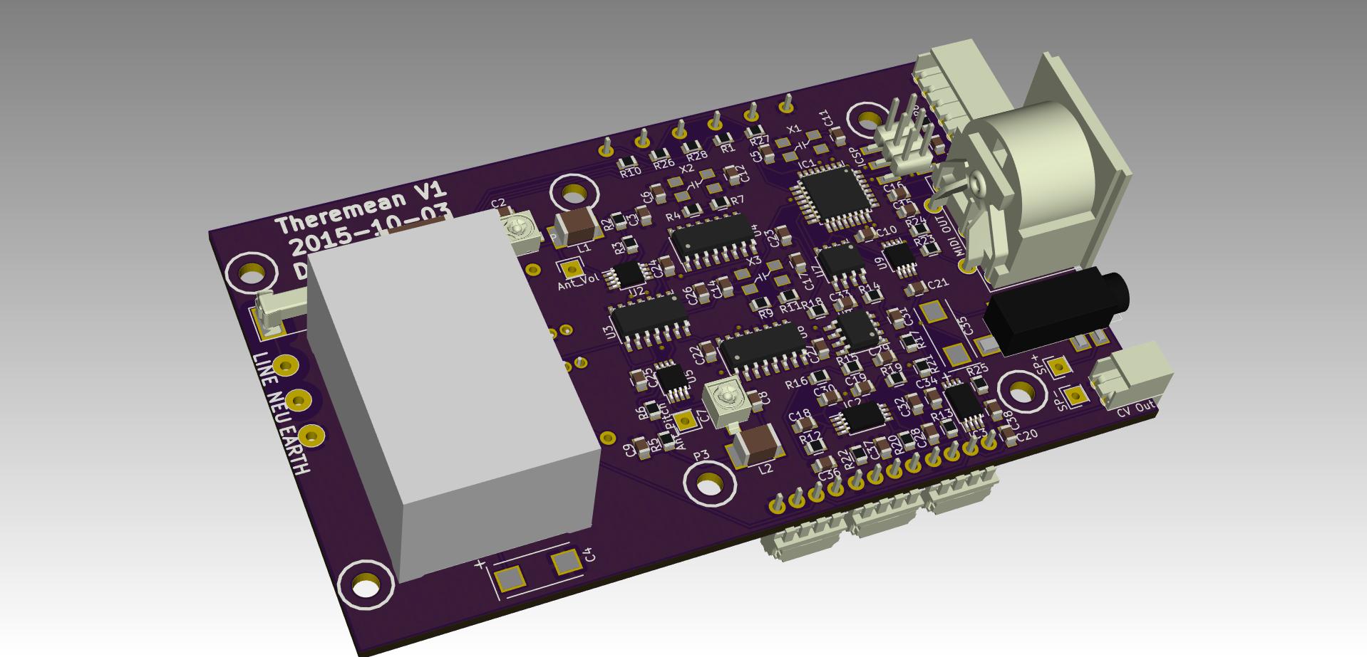
PCB: While I based my KiCAD design on the Open.Theremin.Uno, I made some PCB BOM changes to optimize the components and layout. I also used this as a moment to try my hand at making a board with 0805 passives; while I have experience designing as small as 0402 passives into PCBAs for work, we have those assembled professionally with pick-and-place, and I have never tried something smaller than 1206 for hand-placed SMT work. It turned out fine, and I could have made the layout much tighter if I had wanted to; in fact, in hindsight it looks like I subconsciously left as much spacing as I would have for 1206. I had the PCBs made by the always-awesome OSH Park, and I had a solder paste stencil made by OSH Stencils.
Other Notes: The antennae were made from 5/32″ OD (0.128″ ID) aluminum tubes, hand-shaped and soldered to banana plugs, with some adhesive heatshrink for protection and looks. The mating blue banana jacks were used because I had them on hand already, and I used slider potentiometers with LEDs just to give it some color. I used the original Open.Theremin.Uno Arduino code without any memorable issues; I may have added a few tweaks, I can’t remember.
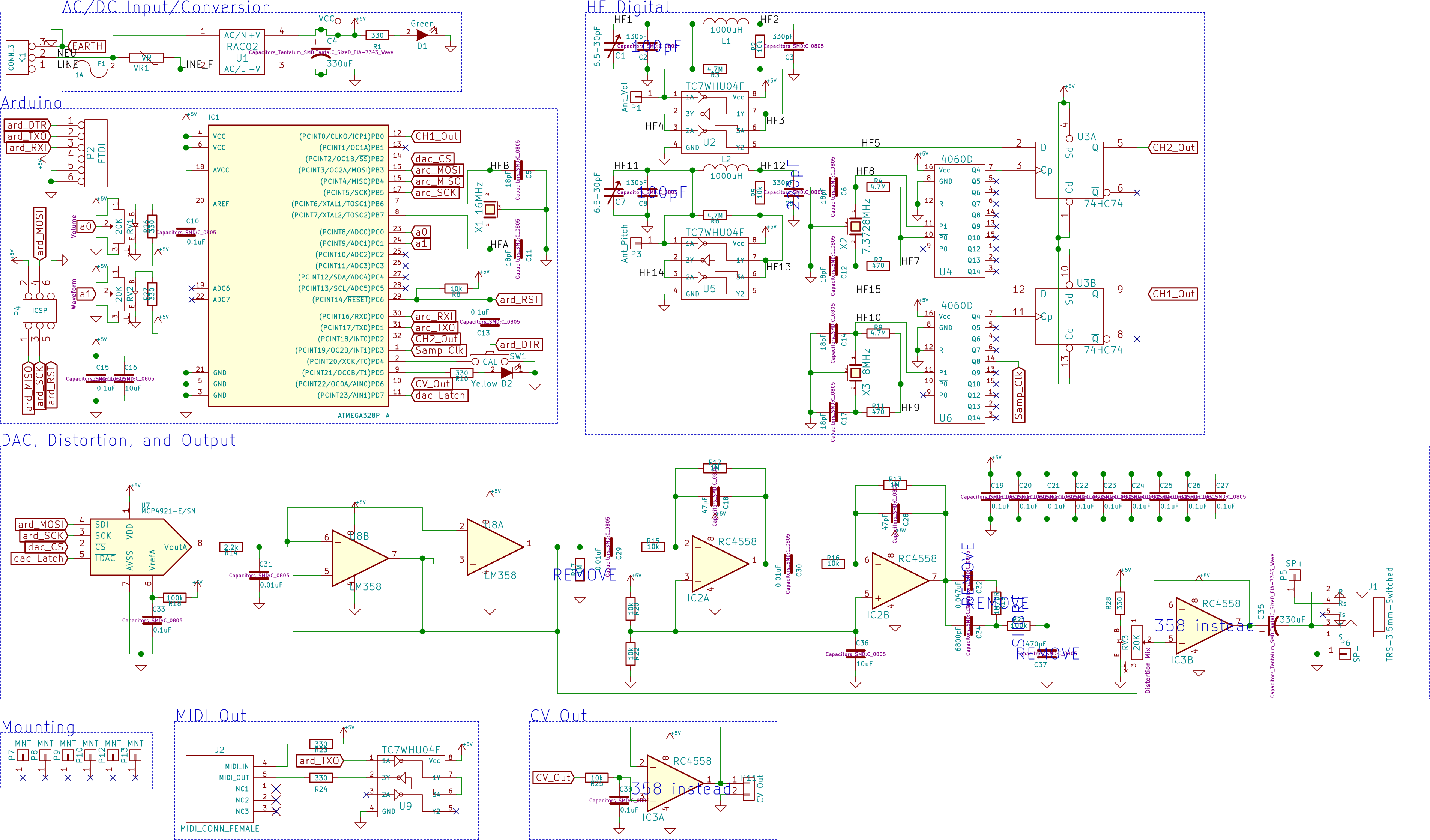
The distortion effect gave me some trouble; I based it on some guitar effects designs I found online, but after the build I discovered some items that needed to be changed, which are noted on the schematic.
I had some trouble with the original tank capacitor values (probably since they were selected for a different PCB design with its own internal capacitances), so I had to solder in some other values in parallel to give me the capacitance I needed to calibrate the unit correctly. An improvement in the future would be to add a digital capacitor IC (a switched capacitor bank, essentially) to allow the calibration to be automatic, because it was rather finicky.
I am happy with the final product. I kept the first one, gave one to my Mom, and gave one to my friend Sean.
UPDATE: Since the completion of this project, an Open.Theremin.V3 has been released with some newer features; most importantly, the automatic calibration that I wanted to include. But they did it with a tuned diode, instead of a switched capacitor bank (digital capacitor) like I proposed.